 Call +91 9833907060
 Send E-mail
![{"uid":"3634C1FA-DF83-4781-886C-1AEFAD51FA45_1625508825429","source":"other","origin":"gallery","sources":[361089331033203]}](https://doshiimpexindia.com/wp-content/uploads/2021/07/image00046-1-scaled-250x250.jpeg "image00046")


The slip-on flange is a simple and excellent alternative to a weld neck as it does not have a weld bevel and therefore allows the pipe to be adjusted in length relative to its position of the flange. The bore of the slip-on will give an ample amount of space for the matching pipe. This allows for enough working space for the Slip-On Flanges Suppliers in Dubai and fabricator to make the connection. The Slip-on flanges Exporter in Dubai is extremely common in lower pressure applications. Most Slip-on flanges in Dubai has a hub that will often appear in a similar dimension to a raised face.
It can be furnished without a hub if space is limited and the application allows for a “ring style” slip on. Although the hub style is more common when referring to a slip on, a ring style slip on without a hub still falls under the category of a slip on flange, and can be called out as you desire. Slip on flanges in UAE are often made with the height of a lap joint for a better connection. If the hub height is not a concern and a lap joint is not readily available, customers will sometimes opt for a slip-on made to a lap joint style with a machined hub.
Our Supply Range:
Standard: ASTM A105, ASTM A182
Material: Carbon Steel, Alloy Steel, Stainless Steel
Size: 1/2” to 24”, customized up to 60”
Pressure Ratings: Class 150 to Class 2500
Face Type: RF, RTJ
Types of Slip On Flange Welding:
The SO flange can be divided into SO welding plate flange and SO welding hubbed steel pipe flange. Its mechanical characteristics are between the integral flange and the looping flange. The structure is simple, and the processing is convenient. So slip on flange welding is widely used in various fluid pipelines.
Depends on different face, there are also ranges raised face type and ring type joint face type.
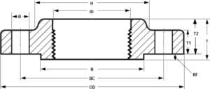
Raised Face Slip On Flange:
There is a small portion extruded from the bottom face of the slip on flange, this type is raised face slip on flange. The function of this area is to place a gasket seat during installation to get a better sealing performance.
As the pressure ratings bigger, the height of this raised face will be bigger.
RTJ Slip on Flange:
A small grooved is machined on the raised face part, this form is called RTJ type, the function of this groove is to place the gasket ring, also applied for sealing, compared to RF type, RTJ is designed for high pressure use.Slip on flange use slip welding to connect equipment, so either below of name is describing the same flange:
- Slip on weld flange
- Slip on flange weld
- Weld slip on flange
- Slip on flange welding
- SO flange
Referred Standard and Grades:
ASTM A105 for carbon steel slip on pipe flanges.
ASTM A182 for alloy and stainless slip on flanges. (Alloy for F11, F22, stainless for F304/F304L, F316/F316L)
ASME B16.5 for pipe flanges and flanged fittings.
BS 3293
DIN 86029
Dimensions and Pressure Ratings:
Common outer diameters: 1/2”, 2”, 3”, 4”, 6”, 8”, 10”, 12”, to 24”.
Special made outer diameters: Up to 60”.
Class range: Class 150, Class 300, 400, 600, 900, 1500, 2500(# or LB). PN 2.5 to PN 250.
Flange face type: RF (Raised Face), RTJ (Ring Type Joint)
Manufacturing Types:
Slip on flange can be made by forging, steel cutting, casting and etc. Among these manufacturing types, the forging type gains the best quality and also the most common use, price is higher than other types. So before purchase the slip on flange, you have to know what is the specific working environment.
Advantages of Slip On Flange:
- Lower installation costs
- More easy to align with other parts during installation
- Better leaking proof
- Inner and outer welding on flange
- Takes less time to cut accurately for the pipelines
- As pipe slides on the flange, it compatible with lower hub on slip on flange
| Nominal | Outside | Thick of | Diameter of | Diameter of | Length | Dia of | No of | Dia of | Dia of | Diam of | Approx |
| Pipe Size | diameter of | flange | Hub at base | raised face | thru Hub | bore | holes | holes | bolts | bolt circle | weight |
| flange | (B) | (A) | (G) | (H) | (ID) | (L) | (K) | kg | |||
| (D) | |||||||||||
| 1/2. | 88.9 | 11.2 | 35.1 | 30.2 | 15.7 | 22.4 | 4 | 15.7 | 1/2. | 60.5 | 0.5 |
| 3/4. | 98.6 | 12.7 | 42.9 | 38.1 | 15.7 | 27.7 | 4 | 15.7 | 1/2. | 69.9 | 1 |
| 1 | 108 | 14.2 | 50.8 | 49.3 | 17.5 | 34.5 | 4 | 15.7 | 1/2. | 79.2 | 1 |
| 1-1/4. | 117.3 | 15.7 | 63.5 | 58.7 | 20.6 | 43.2 | 4 | 15.7 | 1/2. | 88.9 | 1 |
| 1-1/2. | 127 | 17.5 | 73.2 | 65 | 22.4 | 49.5 | 4 | 15.7 | 1/2. | 98.6 | 1 |
| 2 | 152.4 | 19.1 | 91.9 | 77.7 | 25.4 | 62 | 4 | 19.1 | 5/8. | 120.7 | 2 |
| 2-1/2. | 177.8 | 22.4 | 104.6 | 90.4 | 28.4 | 74.7 | 4 | 19.1 | 5/8. | 139.7 | 3 |
| 3 | 190.5 | 23.9 | 127 | 108 | 30.2 | 90.7 | 4 | 19.1 | 5/8. | 152.4 | 4 |
| 3-1/2. | 215.9 | 23.9 | 139.7 | 122.2 | 31.8 | 103.4 | 8 | 19.1 | 5/8. | 177.8 | 5 |
| 4 | 228.6 | 23.9 | 157.2 | 134.9 | 33.3 | 116.1 | 8 | 19.1 | 5/8. | 190.5 | 6 |
| 5 | 254 | 23.9 | 185.7 | 163.6 | 36.6 | 143.8 | 8 | 22.4 | 3/4. | 215.9 | 7 |
| 6 | 279.4 | 25.4 | 215.9 | 192 | 39.6 | 170.7 | 8 | 22.4 | 3/4. | 241.3 | 9 |
| 8 | 342.9 | 28.4 | 269.7 | 246.1 | 44.5 | 221.5 | 8 | 22.4 | 3/4. | 298.5 | 14 |
| 10 | 406.4 | 30.2 | 323.9 | 304.8 | 49.3 | 276.4 | 12 | 25.4 | 7/8. | 362 | 20 |
| 12 | 482.6 | 31.8 | 381 | 365.3 | 55.6 | 327.2 | 12 | 25.4 | 7/8. | 431.8 | 29 |
| 14 | 533.4 | 35.1 | 412.8 | 400.1 | 57.2 | 359.2 | 12 | 28.4 | 1 | 476.3 | 41 |
| 16 | 596.9 | 36.6 | 469.9 | 457.2 | 63.5 | 410.5 | 16 | 28.4 | 1 | 539.8 | 44 |
| 18 | 635 | 39.6 | 533.4 | 505 | 68.3 | 461.8 | 16 | 31.8 | 1-1/8. | 577.9 | 59 |
| 20 | 698.5 | 42.9 | 584.2 | 558.8 | 73.2 | 513.1 | 20 | 31.8 | 1-1/8. | 635 | 75 |
| 24 | 812.8 | 47.8 | 692.2 | 663.4 | 82.6 | 616 | 20 | 35.1 | 1-1/4. | 749.3 | 100 |
|
Dimensions of Class 300 Slip-On Flanges |
| Nominal | Outside | Thick of | Diameter of | Diameter of | Length | Dia of | No of | Dia of | Dia of | Diam of | Approx |
| Pipe Size | diameter of | flange | Hub at base | raised face | thru Hub | bore | holes | holes | bolts | bolt circle | weight |
| flange | (B) | (A) | (G) | (H) | (ID) | (L) | (K) | kg | |||
| (D) | |||||||||||
| 1/2. | 95.3 | 14.2 | 35.1 | 38.1 | 22.4 | 22.4 | 4 | 15.7 | 1/2. | 66.5 | 1 |
| 3/4. | 117.3 | 15.7 | 42.9 | 47.8 | 25.4 | 27.7 | 4 | 19.1 | 5/8. | 82.6 | 1 |
| 1 | 124 | 17.5 | 50.8 | 53.8 | 26.9 | 34.5 | 4 | 19.1 | 5/8. | 88.9 | 1 |
| 1-1/4. | 133.4 | 19.1 | 63.5 | 63.5 | 26.9 | 43.2 | 4 | 19.1 | 5/8. | 98.6 | 2 |
| 1-1/2. | 155.4 | 20.6 | 73.2 | 69.9 | 30.2 | 49.5 | 4 | 22.4 | 3/4. | 114.3 | 3 |
| 2 | 165.1 | 22.4 | 91.9 | 84.1 | 33.3 | 62 | 8 | 19.1 | 5/8. | 127 | 3 |
| 2-1/2. | 190.5 | 25.4 | 104.6 | 100.1 | 38.1 | 74.7 | 8 | 22.4 | 3/4. | 149.4 | 5 |
| 3 | 209.6 | 28.4 | 127 | 117.3 | 42.9 | 90.7 | 22.4 | 8 | 3/4. | 168.1 | 6 |
| 3-1/2. | 228.6 | 30.2 | 139.7 | 133.4 | 44.5 | 103.4 | 22.4 | 8 | 3/4. | 184.2 | 8 |
| 4 | 254 | 31.8 | 157.2 | 146.1 | 47.8 | 116.1 | 8 | 22.4 | 3/4. | 200.2 | 10 |
| 5 | 279.4 | 35.1 | 185.7 | 177.8 | 50.8 | 143.8 | 8 | 22.4 | 3/4. | 235 | 13 |
| 6 | 317.5 | 36.6 | 215.9 | 206.2 | 52.3 | 170.7 | 12 | 22.4 | 3/4. | 269.7 | 18 |
| 8 | 381 | 41.1 | 269.7 | 260.4 | 62 | 221.5 | 12 | 25.4 | 73/93 | 330.2 | 26 |
| 10 | 444.5 | 47.8 | 323.9 | 320.5 | 66.5 | 276.4 | 16 | 28.4 | 1 | 387.4 | 37 |
| 12 | 520.7 | 50.8 | 381 | 374.7 | 73.2 | 327.2 | 16 | 31.8 | 1-1/8. | 450.9 | 52 |
| 14 | 584.2 | 53.8 | 412.8 | 425.5 | 76.2 | 359.2 | 20 | 31.8 | 1-1/8. | 514.4 | 75 |
| 16 | 647.7 | 57.2 | 469.9 | 482.6 | 82.6 | 410.5 | 20 | 35.1 | 1-1/4. | 571.5 | 86 |
| 18 | 711.2 | 60.5 | 533.4 | 533.4 | 88.9 | 461.8 | 24 | 35.1 | 1-1/4. | 628.7 | 113 |
| 20 | 774.7 | 63.5 | 584.2 | 587.2 | 95.3 | 513.1 | 24 | 35.1 | 1-1/4. | 685.8 | 143 |
| 24 | 914.4 | 69.9 | 692.2 | 701.5 | 106.4 | 616 | 24 | 41.1 | 1-1/2. | 812.8 | 215 |
|
Dimensions of Class 600 Slip-On Flanges |
| Nominal | Outside | Thick of | Diameter of | Diameter of | Length | Dia of | No of | Dia of | Dia of | Diam of | Approx |
| Pipe Size | diameter of | flange | Hub at base | raised face | thru Hub | bore | holes | holes | bolts | bolt circle | weight |
| flange | (B) | (A) | (G) | (H) | (ID) | (L) | (K) | kg | |||
| (D) | |||||||||||
| 1/2. | 95.3 | 14.2 | 35.1 | 38.1 | 22.4 | 22.4 | 4 | 15.7 | 1/2. | 66.5 | 1 |
| 3/4. | 117.3 | 15.7 | 42.9 | 47.8 | 25.4 | 27.7 | 4 | 19.1 | 5/8. | 82.6 | 1 |
| 1 | 124 | 17.5 | 50.8 | 53.8 | 26.9 | 34.5 | 4 | 19.1 | 5/8. | 88.9 | 2 |
| 1-1/4. | 133.4 | 20.6 | 63.5 | 63.5 | 28.4 | 43.2 | 4 | 19.1 | 5/8. | 98.6 | 2 |
| 1-1/2. | 155.4 | 22.4 | 73.2 | 69.9 | 31.8 | 49.5 | 4 | 22.4 | 3/4. | 114.3 | 3 |
| 2 | 165.1 | 25.4 | 91.9 | 84.1 | 36.6 | 62 | 8 | 19.1 | 5/8. | 127 | 4 |
| 2-1/2. | 190.5 | 28.4 | 104.6 | 100.1 | 41.1 | 74.7 | 8 | 22.4 | 3/4. | 149.4 | 6 |
| 3 | 209.6 | 31.8 | 127 | 117.3 | 46 | 90.7 | 8 | 22.4 | 3/4. | 168.1 | 7 |
| 3-1/2. | 228.6 | 35.1 | 139.7 | 133.4 | 49.3 | 103.4 | 8 | 25.4 | 7/8. | 184.2 | 10 |
| 4 | 273.1 | 38.1 | 157.2 | 152.4 | 53.8 | 116.1 | 8 | 25.4 | 7/8. | 215.9 | 17 |
| 5 | 330.2 | 44.5 | 185.7 | 189 | 60.5 | 143.8 | 8 | 28.4 | 1 | 266.7 | 29 |
| 8 | 419.1 | 55.6 | 269.7 | 273.1 | 76.2 | 221.5 | 12 | 31.8 | 1-1/8. | 349.3 | 52 |
| 10 | 508 | 63.5 | 323.9 | 342.9 | 85.9 | 276.4 | 16 | 35.1 | 1-1/4. | 431.8 | 77 |
| 12 | 558.8 | 66.5 | 381 | 400.1 | 91.9 | 327.2 | 20 | 35.1 | 1-1/4. | 489 | 91 |
| 14 | 603.3 | 69.9 | 412.8 | 431.8 | 93.7 | 359.2 | 20 | 38.1 | 1-3/8. | 527.1 | 104 |
| 16 | 685.8 | 76.2 | 469.9 | 495.3 | 106.4 | 410.5 | 20 | 41.1 | 1-1/2. | 603.3 | 150 |
| 18 | 743 | 82.6 | 533.4 | 546.1 | 117.3 | 461.8 | 20 | 44.5 | 1-5/8. | 654.1 | 181 |
| 20 | 812.8 | 88.9 | 584.2 | 609.6 | 127 | 513.1 | 24 | 44.5 | 1-5/8. | 723.9 | 231 |
| 24 | 939.8 | 101.6 | 692.2 | 717.6 | 139.7 | 616 | 24 | 50.8 | 1-7/8. | 838.2 | 331 |
|
Dimensions of Class 900 Slip-On Flanges |
|||||||||||
| Nominal | Outside | Thick of | Diameter of | Diameter of | Length | Dia of | No of | Dia of | Dia of | Diam of | Approx |
| Pipe Size | diameter of | flange | Hub at base | raised face | thru Hub | bore | holes | holes | bolts | bolt circle | weight |
| flange | (B) | (A) | (G) | (H) | (ID) | (L) | (K) | kg | |||
| (D) | |||||||||||
| 1/2. | 120.7 | 22.4 | 35.1 | 38.1 | 31.8 | 22.4 | 4 | 22.4 | 3/4. | 82.6 | 2 |
| 3/4. | 130 | 25.4 | 42.9 | 44.5 | 35.1 | 27.7 | 4 | 22.4 | 3/4. | 88.9 | 2 |
| 1 | 149.4 | 28.4 | 50.8 | 52.3 | 41.1 | 34.5 | 4 | 25.4 | 7/8. | 101.6 | 4 |
| 1-1/4. | 158.8 | 28.4 | 63.5 | 63.5 | 41.1 | 43.2 | 4 | 25.4 | 7/8. | 111.3 | 4 |
| 1-1/2. | 177.8 | 31.8 | 73.2 | 69.9 | 44.5 | 49.5 | 4 | 28.4 | 1 | 124 | 5 |
| 2 | 215.9 | 38.1 | 91.9 | 104.6 | 57.2 | 62 | 8 | 25.4 | 7/8. | 165.1 | 11 |
| 2-1/2. | 244.3 | 41.1 | 104.6 | 124 | 63.5 | 74.7 | 8 | 28.4 | 1 | 190.5 | 16 |
| 3 | 241.3 | 38.1 | 127 | 127 | 53.8 | 90.7 | 8 | 25.4 | 7/8. | 190.5 | 12 |
| 4 | 292.1 | 44.5 | 157.2 | 158.8 | 69.9 | 116.1 | 8 | 31.8 | 1-1/8. | 235 | 24 |
| 5 | 349.3 | 50.8 | 185.7 | 190.5 | 79.2 | 143.8 | 8 | 35.1 | 1-1/4. | 279.4 | 38 |
| 6 | 381 | 55.6 | 215.9 | 235 | 85.9 | 170.7 | 31.8 | 12 | 1-1/8. | 317.5 | 50 |
| 8 | 469.9 | 63.5 | 269.7 | 298.5 | 101.6 | 221.5 | 12 | 38.1 | 1-3/8. | 393.7 | 77 |
| 10 | 546.1 | 69.9 | 323.9 | 368.3 | 108 | 276.4 | 16 | 38.1 | 1-3/8. | 469.9 | 111 |
| 12 | 609.6 | 79.2 | 381 | 419.1 | 117.3 | 327.2 | 20 | 38.1 | 1-3/8. | 533.4 | 147 |
| 14 | 641.4 | 85.9 | 412.8 | 450.9 | 130 | 359.2 | 20 | 41.1 | 1-1/2. | 558.8 | 181 |
| 16 | 704.9 | 88.9 | 469.9 | 508 | 133.4 | 410.5 | 20 | 44.5 | 1-5/8. | 41.3 | 616 |
| 18 | 787.4 | 101.6 | 533.4 | 565.2 | 152.4 | 461.8 | 20 | 50.8 | 1-7/8. | 685.8 | 272 |
| 20 | 857.3 | 108 | 584.2 | 622.3 | 158.8 | 513.1 | 20 | 53.8 | 2 | 749.3 | 331 |
| 24 | 1041.4 | 139.7 | 692.2 | 749.3 | 203.2 | 616 | 20 | 66.5 | 2-1/2. | 901.7 | 635 |
|
Dimensions of Class 1500 Slip-On Flanges |
|||||||||||
| Nominal | Outside | Thick of | Diameter of | Diameter of | Length | Dia of | No of | Dia of | Dia of | Diam of | Approx |
| Pipe Size | diameter of | flange | Hub at base | raised face | thru Hub | bore | holes | holes | bolts | bolt circle | weight |
| flange | (B) | (A) | (G) | (H) | (ID) | (L) | (K) | kg | |||
| (D) | |||||||||||
| 1/2. | 120.7 | 22.4 | 35.1 | 38.1 | 31.8 | 22.4 | 4 | 22.4 | 3/4. | 82.6 | 2 |
| 3/4. | 130 | 25.4 | 42.9 | 44.5 | 35.1 | 27.7 | 4 | 22.4 | 3/4. | 88.9 | 2 |
| 1 | 149.4 | 28.4 | 50.8 | 52.3 | 41.1 | 34.5 | 4 | 25.4 | 7/8. | 101.6 | 4 |
| 1-1/4. | 158.8 | 28.4 | 63.5 | 63.5 | 41.1 | 43.2 | 4 | 25.4 | 7/8. | 111.3 | 4 |
| 1-1/2. | 177.8 | 31.8 | 73.2 | 69.9 | 44.5 | 49.5 | 4 | 28.4 | 1 | 124 | 5 |
| 2 | 215.9 | 38.1 | 91.9 | 104.6 | 57.2 | 62 | 8 | 25.4 | 7/8. | 165.1 | 11 |
| 2-1/2. | 244.3 | 41.1 | 104.6 | 124 | 63.5 | 74.7 | 8 | 28.4 | 1 | 190.5 | 16 |
| 3 | 266.7 | 47.8 | 127 | 133.4 | 73.2 | – | 8 | 31.8 | 1-1/8. | 203.2 | 22 |
| 4 | 311.2 | 53.8 | 157.2 | 162.1 | 90.4 | – | 8 | 35.1 | 1-1/4. | 241.3 | 33 |
| 5 | 374.7 | 73.2 | 185.7 | 196.9 | 104.6 | – | 8 | 41.1 | 1-1/2. | 292.1 | 59 |
| 6 | 393.7 | 82.6 | 215.9 | 228.6 | 119.1 | – | 12 | 38.1 | 1-3/8. | 317.5 | 75 |
| 8 | 482.6 | 91.9 | 269.7 | 292.1 | 142.7 | – | 12 | 44.5 | 1-5/8. | 393.7 | 118 |
| 10 | 584.2 | 108 | 323.9 | 368.3 | 158.8 | – | 12 | 50.8 | 1-7/8. | 482.6 | 197 |
| 12 | 673.1 | 124 | 381 | 450.9 | 180.8 | – | 16 | 53.8 | 2 | 571.5 | 263 |
| 14 | 749.3 | 133.4 | 412.8 | 495.3 | – | – | 16 | 60.5 | 2-1/4. | 635 | – |
| 16 | 825.5 | 146.1 | 469.9 | 552.5 | – | – | 16 | 66.5 | 2-1/2. | 704.9 | – |
| 18 | 914.4 | 162.1 | 533.4 | 596.9 | – | – | 16 | 73.2 | 2-3/4. | 774.7 | – |
| 20 | 984.3 | 177.8 | 584.2 | 641.4 | – | – | 16 | 79.2 | 3 | 831.9 | – |
| 24 | 1168.4 | 203.2 | 692.2 | 762 | – | – | 16 | 91.9 | 3-1/2. | 990.6 | – |