![image00045 {"uid":"3634C1FA-DF83-4781-886C-1AEFAD51FA45_1625508825429","source":"other","origin":"gallery","sources":[361089331033203]}](https://doshiimpexindia.com/wp-content/uploads/2021/07/image00045-1-scaled-250x250.jpeg)

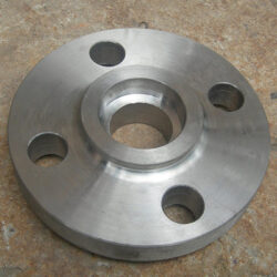
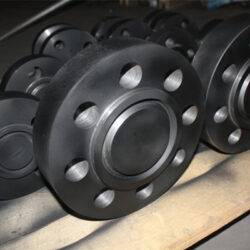
SW Flange (Socket Weld Flange) contains a shoulder on the inside of the flange that acts as a guide to set the depth at which the pipe is welded to the flange. Flanges socket weld flanges Exporter in Dubai is fabricated by inserting the pipe end into the flange until it bottoms out against the shoulder and then retracting the pipe 1/8 in before welding it in place. This practice was originally employed to reduce cracking due to thermal stresses in stainless steel superheaters, but over the years has become standard practice for the installation of all socket weld flanges (SW Flange).On the socket weld flange, you have to specify the pipe schedule. The pipe schedule, is a 2-inch nominal pipe, and this is a standard schedule pipe, and this is a standard schedule socket weld. The pipe schedule and the bore of the socket weld flange have to match so that there is no raised face, there is no protrusion on the backside. The difference between a Flanges socket weld flanges Stockist in Dubai has a bore of schedule 40 or schedule 80 is that this inner bore will change so it matches the bore of the pipe. That’s what you’re trying to do. Flanges socket weld flanges in Dubai is simplified as SW flange, it has a recessed area (like a shoulder) in the flange bore, this shoulder serves as a guide to set the depth of the pipe that is inserted into the flange. Socket welding flange was initially designed for a high-pressure small diameters piping system.
Available Material:
Standard:
Carbon steel ASTM A105, ASTM A350 LF1/2, ASTM A181
Alloy steel ASTM A182 F5, F9, F11, F22, F91
Stainless steel ASTM A182 F304/L, F316/L
Outer Diameters: 1/2 inch to 24 inches, up to 2500#
Special made: 24” to 60”, up to 900#
Wall Thickness: Schedule 40 to 160
Pressure Ratings: Class 150 to Class 2500
Face Type: RF, RTJ
How to Use:
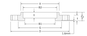
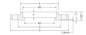
Insert the pipe end into socket weld flange, until the pipe bottom touches the shoulder area, pull back 1.6mm (1/16”) distance of the inserted pipe then do fillet welding. The point is to create an expansion gap (1 fillet weld) between the flange and the pipes or fittings.
How is Socket Welding Flange Generated:
The socket welding flange was firstly used for stainless steel superheater, due to avoid cracking defects caused by thermal stresses in heating processes, and after years of development, it became standard applications for all types of material.
Socket Welded Flange Face Types:
Socket welded flange including RF type and RTJ type, which are like other types of welding flanges (slip-on, weld neck, or blind flange).
RF Type
RF socket weld flange has a small portion surrounding the flange bore that protrudes from the face. A gasket seat will be placed in this raised area.
RTJ Type
On the raised face surface there has a groove is RTJ type, which you can place a gasket ring to get better sealing performances.
Advantages
- Socket weld flange could replace threaded flange, to minimize the risky of leakage.
- No need to beveling before welding.
- Welding work outside of the pipe, will not penetrate the pipe bore
- It is recommended for applications where internal welding operations are particularly difficult. This sock welded construction eliminates internal pockets while avoiding warpage of welding heat and damage to the flange face caused by the weld spatter. It has the same internal pressure as the sliding on the flange and has a better fatigue life.
SOCKET WELD FLANGE DIMENSIONS IN MILLIMETERS
SOCKET WELD CLASS 150 (IN MM)
Socket weld flange dimensions class 150 in millimeters (ASME B16.5)

| Size | D | X | G | t | B1 | B2 | T2 | Y |
| inch | mm | mm | mm | mm | mm | mm | mm | mm |
| 1/2. | 89 | 30.2 | 35.1 | 11.2 | 15.7 | 22.4 | 15.7 | 9.7 |
| 3/4. | 99 | 38.1 | 42.9 | 12.7 | 20.8 | 27.7 | 15.7 | 11.2 |
| 1 | 108 | 49.3 | 50.8 | 14.2 | 26.7 | 34.5 | 17.5 | 12.7 |
| 1¼ | 117 | 58.7 | 63.5 | 15.7 | 35.1 | 43.2 | 20.6 | 14.2 |
| 1½ | 127 | 65 | 73.2 | 17.5 | 40.9 | 49.5 | 22.4 | 15.7 |
| 2 | 152 | 77.7 | 91.9 | 19.1 | 52.6 | 62 | 25.4 | 17.5 |
| 2½ | 178 | 90.4 | 104.6 | 22.4 | 62.7 | 74.7 | 28.4 | 19.1 |
| 3 | 191 | 108 | 127 | 23.9 | 78 | 90.7 | 30.2 | 20.6 |
| 3½ | 216 | 122.2 | 139.7 | 23.9 | 90.2 | 103.4 | 31.8 | 22.4 |
| 4 | 229 | 134.9 | 157.2 | 23.9 | 102.4 | 116.1 | 33.3 | 23.9 |
| 5 | 254 | 163.6 | 185.7 | 23.9 | 128.3 | 143.8 | 36.6 | 23.9 |
| 6 | 279 | 192 | 215.9 | 25.4 | 154.2 | 170.7 | 39.6 | 26.9 |
| 8 | 343 | 246.1 | 269.7 | 28.4 | 202.7 | 221.5 | 44.5 | 31.8 |
| 10 | 406 | 304.8 | 323.9 | 30.2 | 254.5 | 276.4 | 49.3 | 33.3 |
| 12 | 483 | 365.3 | 381 | 31.8 | 304.8 | 327.2 | 55.6 | 39.6 |
| 14 | 533 | 400.1 | 412.8 | 35.1 | 336.6 | 359.2 | 57.2 | 41.4 |
| 16 | 597 | 457.2 | 469.9 | 36.6 | 387.4 | 410.5 | 63.5 | 44.5 |
| 18 | 635 | 505 | 533.4 | 39.6 | 438.2 | 461.8 | 68.3 | 49.3 |
| 20 | 699 | 558.8 | 584.2 | 42.9 | 489 | 513.1 | 73.2 | 54.1 |
| 24 | 813 | 663.4 | 692.2 | 47.8 | 590.6 | 616 | 82.6 | 63.5 |
|
SOCKET WELD CLASS 300 (IN MM) |
Socket weld flange dimensions class 300 in millimeters (ASME B16.5)
| Size | D | X | G | t | B1 | B2 | T2 | Y |
| inch | mm | mm | mm | mm | mm | mm | mm | mm |
| 1/2. | 95 | 38.1 | 35.1 | 14.2 | 15.7 | 22.4 | 22.4 | 9.7 |
| 3/4. | 117 | 47.8 | 42.9 | 15.7 | 20.8 | 27.7 | 25.4 | 11.2 |
| 1 | 124 | 53.8 | 50.8 | 17.5 | 26.7 | 34.5 | 26.9 | 12.7 |
| 1¼ | 133 | 63.5 | 63.5 | 19.1 | 35.1 | 43.2 | 26.9 | 14.2 |
| 1½ | 155 | 69.9 | 73.2 | 20.6 | 40.9 | 49.5 | 30.2 | 15.7 |
| 2 | 165 | 84.1 | 91.9 | 22.4 | 52.6 | 62 | 33.3 | 17.5 |
| 2½ | 191 | 100.1 | 104.6 | 25.4 | 62.7 | 74.7 | 38.1 | 19.1 |
| 3 | 210 | 117.3 | 127 | 28.4 | 78 | 90.7 | 42.9 | 20.6 |
| 3½ | 229 | 133.4 | 139.7 | 30.2 | 90.2 | 103.4 | 44.5 | 22.4 |
| 4 | 254 | 146.1 | 157.2 | 31.8 | 102.4 | 116.1 | 47.8 | 23.9 |
| 5 | 279 | 177.8 | 185.7 | 35.1 | 128.3 | 143.8 | 50.8 | 23.9 |
| 6 | 318 | 206.2 | 215.9 | 36.6 | 154.2 | 170.7 | 52.3 | 26.9 |
| 8 | 381 | 260.4 | 269.7 | 41.1 | 202.7 | 221.5 | 62 | 31.8 |
| 10 | 445 | 320.5 | 323.9 | 47.8 | 254.5 | 276.4 | 66.5 | 33.3 |
| 12 | 521 | 374.7 | 381 | 50.8 | 304.8 | 327.2 | 73.2 | 39.6 |
| 14 | 584 | 425.5 | 412.8 | 63.8 | 336.6 | 359.2 | 76.2 | 41.4 |
| 16 | 648 | 482.6 | 469.9 | 57.2 | 387.4 | 410.5 | 82.6 | 44.5 |
| 18 | 711 | 533.4 | 533.4 | 60.5 | 438.2 | 461.8 | 88.9 | 49.3 |
| 20 | 775 | 587.2 | 584.2 | 63.5 | 489 | 513.1 | 95.3 | 54.1 |
| 24 | 914 | 701.5 | 692.2 | 69.9 | 590.6 | 616 | 106.4 | 63.5 |
| SOCKET WELD CLASS 600 (IN MM) | ||||||||
| Socket weld flange dimensions class 600 in millimeters (ASME B16.5) | ||||||||
| Size | D | X | G | t | B1 | B2 | T2 | Y |
| inch | mm | mm | mm | mm | mm | mm | mm | mm |
| 1/2. | 95 | 38.1 | 35.1 | 14.2 | B36.10/.19 | 22.4 | 22.4 | 9.7 |
| 3/4. | 117 | 47.8 | 42.9 | 15.7 | B36.10/.19 | 27.7 | 25.4 | 11.2 |
| 1 | 124 | 53.8 | 50.8 | 17.5 | B36.10/.19 | 34.5 | 26.9 | 12.7 |
| 1¼ | 133 | 63.5 | 63.5 | 20.6 | B36.10/.19 | 43.2 | 28.4 | 14.2 |
| 1½ | 155 | 69.9 | 73.2 | 22.4 | B36.10/.19 | 49.5 | 31.8 | 15.7 |
| 2 | 165 | 84.1 | 91.9 | 25.4 | B36.10/.19 | 62 | 36.6 | 17.5 |
| 2½ | 191 | 100.1 | 104.6 | 28.4 | B36.10/.19 | 74.7 | 41.1 | 19.1 |
| 3 | 210 | 117.3 | 127 | 31.8 | B36.10/.19 | 90.7 | 46 | 20.6 |
| 3½ | 229 | 133.4 | 139.7 | 35.1 | B36.10/.19 | 103.4 | 49.3 | 22.4 |
| 4 | 273 | 152.4 | 157.2 | 38.1 | B36.10/.19 | 116.1 | 53.8 | 23.9 |
| 5 | 330 | 189 | 185.7 | 44.5 | B36.10/.19 | 143.8 | 60.5 | 23.9 |
| 6 | 356 | 222.3 | 215.9 | 47.8 | B36.10/.19 | 170.7 | 66.5 | 26.9 |
| 8 | 419 | 273.1 | 269.7 | 55.6 | B36.10/.19 | 221.5 | 76.2 | 31.8 |
| 10 | 508 | 342.9 | 323.9 | 63.5 | B36.10/.19 | 276.4 | 85.9 | 33.3 |
| 12 | 559 | 400.1 | 381 | 66.5 | B36.10/.19 | 327.2 | 91.9 | 39.6 |
| 14 | 603 | 431.8 | 412.8 | 69.9 | B36.10/.19 | 359.2 | 93.7 | 41.4 |
| 16 | 686 | 495.3 | 469.9 | 76.2 | B36.10/.19 | 410.5 | 106.4 | 44.5 |
| 18 | 743 | 546.1 | 533.4 | 82.6 | B36.10/.19 | 461.8 | 117.3 | 49.3 |
| 20 | 813 | 609.6 | 584.2 | 88.9 | B36.10/.19 | 513.1 | 127 | 54.1 |
| 24 | 940 | 717.6 | 692.2 | 101.6 | B36.10/.19 | 616 | 139.7 | 63.5 |
|
Dimensions of Class 1500 RF Socket Weld Flanges |
|||||||||
|
All dimensions are in “mm” unless noted otherwise. |
|||||||||
|
Dimensions of Class 1500 RF Socket Weld Flanges as per ASME B16.5. |

| Nominal | Outside Dia | Thick of | Dia of | Dia of | Length | Dia of | Depth of | No of | Dia of | Dia of | Dia of | Approx |
| size | of Flange | Flange | Raised Face | Hub at Base | thru Hub | Bore | Socket | Holes | Holes | Bolts | Bolt Circle | Weight |
| (D) | (B) | (G) | (A) | (H) | (ID) | (F) | (L) | (K) | (kg) | |||
| 1/2. | 120.7 | 22.4 | 35.1 | 38.1 | 31.8 | 22.4 | 9.7 | 4 | 22.4 | 3/4. | 82.6 | 2 |
| 3/4. | 130 | 25.4 | 42.9 | 44.5 | 35.1 | 27.7 | 11.2 | 4 | 22.4 | 3/4. | 88.9 | 2 |
| 1 | 149.4 | 28.4 | 50.8 | 52.3 | 41.1 | 34.5 | 12.7 | 4 | 25.4 | 7/8. | 101.6 | 4 |
| 1-1/4. | 158.8 | 28.4 | 63.5 | 63.5 | 41.1 | 43.2 | 14.2 | 4 | 25.4 | 7/8. | 111.3 | 4 |
| 1-1/2. | 177.8 | 31.8 | 73.2 | 69.9 | 44.5 | 49.5 | 15.7 | 4 | 28.4 | 1 | 124 | 5 |
| 2 | 215.9 | 38.1 | 91.9 | 104.6 | 57.2 | 62 | 17.5 | 8 | 25.4 | 7/8. | 165.1 | 11 |
| 2-1/2. | 244.3 | 41.1 | 104.6 | 124 | 63.5 | 74.7 | 8 | 19.1 | 28.4 | 1 | 190.5 | 16 |
| 3 | 266.7 | 47.8 | 127 | 133.4 | 73.2 | – | – | 8 | 31.8 | 1-1/8. | 203.2 | 22 |
| 4 | 311.2 | 53.8 | 157.2 | 162.1 | 90.4 | – | – | 8 | 35.1 | 1-1/4. | 241.3 | 33 |
| 5 | 374.7 | 73.2 | 185.7 | 196.9 | 104.6 | – | – | 8 | 41.1 | 1-1/2. | 292.1 | 59 |
| 6 | 393.7 | 82.6 | 215.9 | 228.6 | 119.1 | – | – | 12 | 38.1 | 1-3/8. | 317.5 | 75 |
| 8 | 482.6 | 91.9 | 269.7 | 292.1 | 142.7 | – | – | 12 | 44.5 | 1-5/8. | 393.7 | 118 |
| 10 | 584.2 | 108 | 323.9 | 368.3 | 158.8 | – | – | 12 | 50.8 | 1-7/8. | 482.6 | 197 |
| 12 | 673.1 | 124 | 381 | 450.9 | 180.8 | – | – | 16 | 53.8 | 2 | 571.5 | 263 |
| 14 | 749.3 | 133.4 | 412.8 | 495.3 | – | – | – | 16 | 60.5 | 2-1/4. | 635 | |
| 16 | 825.5 | 146.1 | 469.9 | 552.5 | – | – | – | 16 | 66.5 | 2-1/2. | 704.9 | |
| 18 | 914.4 | 162.1 | 533.4 | 596.9 | – | – | – | 16 | 73.2 | 2-3/4. | 774.7 | |
| 20 | 984.3 | 177.8 | 584.2 | 641.4 | – | – | – | 16 | 79.2 | 3 | 831.9 | |
| 24 | 1168.4 | 203.2 | 692.2 | 762 | – | – | – | 16 | 91.9 | 3-1/2. | 990.6 |
 Call +91 9833907060
 Send E-mail